
The best tools for rapid prototyping and inspection are here!
Competition in the aerospace industry has never been greater, and any slight advantage can enhance the likelihood of winning a contract or increasing profitability. This is particularly true in the Maintenance, Repair, and Overhaul (MRO) sector, where the faster and more accurately you can repair and certify components during routine maintenance checks, the more work you can take on. Thus, the more financially successful your business can be. Today we are going to explore a few 3D solutions for aerospace MRO workflows that could streamline your company’s current workflow.

First, a little about our Central Florida company and why you should lean on us for your technological exploration. 2023 marks our 20-year anniversary, our company being founded by Dan Perreault. A well-respected name in the industry, Dan began his career as an Applications Engineer with FARO Technologies, where he helped develop what was initially a device used to measure human spinal curvature into a household…er…shopfloor name that became inextricably linked with metrology.
At NeoMetrix, we offer both engineering services and product sales of complete 3D solutions, partnering with industry giants like Oqton (formerly Geomagic), Creafrom, PolyWorks, Markforged, Big Rep, INTAMSYS, and Ansys to offer a wide range of 3D scanning and printing technologies matched to the perfect software solution for your application.
Our Mission: To partner with our clients by understanding their unique requirements and aid in developing, deploying, and supporting effective solutions.

We don’t sell boxes, we custom tailor solutions for each distinctive application, then provide ongoing training and support. The reputation we garner has led to a vast and diverse customer base across not just the aerospace industry, but also automotive, medical, nautical, defense, entertainment, educational, and more.
Today we will be presented with a common 3D scanning aerospace application from start to finish, showcasing a complete progression across our 3D scanning, reverse engineering, and inspection workflows. We will then explore a handful of NeoMetrix customer success stories that parallel this application and showcase how our technology has been applied across the industry.
So, imagine putting yourself into the following scenario: you’re a Quality Control manager at an aerospace MRO service provider, and you’ve just won an outstanding contract for ongoing inspection and maintenance for aircraft engine components, to include the propeller blades. These need to be checked for excessive wear, warpage, and damage at specified intervals where the option to repair or replace will be assessed. The aircraft in question has been in service for many years. Enough, in fact, that up-to-date 3D CAD data does not exist for the plane, and the manufacturer only provides a 2D drawing with a handful of dimensioned features, airfoil cross sections, and an overall surface profile. The responsibility, therefore, falls on you to determine how validation of each blade is to be carried out.
Our team at NeoMetrix specializes in consulting on the best solution for your workflow and industry. In short, the process will look like this:
1.We 3D scan a “gold standard” blade…preferably a new one that has been previously certified.
2. We reverse engineer the blade from our 3D scan data into a parametric 3D model.
3. We utilize our new 3D model for inspection of each worn blade that we receive, and hopefully manufacture new replacements for blades damaged beyond repair.
HandySCAN Black Elite - 3D Scanner
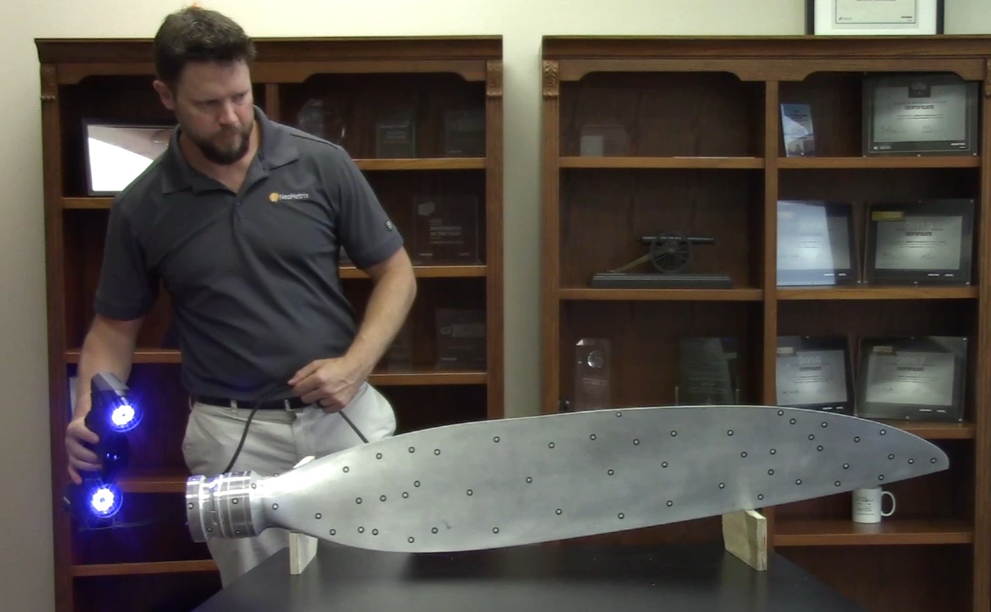
For rapidly capturing the surface data of the blade while maintaining ultimate portability and accuracy, our flagship Creaform HandySCAN Black|Elite Limited scanner is our best possible solution. At two pounds, it is small enough to be carried anywhere in a suitcase yet one of the fastest 3D scanners ever built and sports an accuracy of 12 microns (0.0005”) and is uniquely ISO 17025 accredited.

The HandySCAN Black Elite utilizes reflective targets placed on or around the part, allowing the scanner to track its movements through space. A pre-targeted workstation can be used on smaller objects for the ultimate speed in setup, yet the advantage gained by targeting the part is that scanning can be done in a dynamic environment without loss of accuracy. For situations where components must be scanned while remaining installed, we are no longer required to halt the tasks of other maintenance crews, as part movement and vibration no longer affects our ability to gather data…truly a shop-floor metrology solution.


Go from 3D Scan-to-CAD faster than ever before!
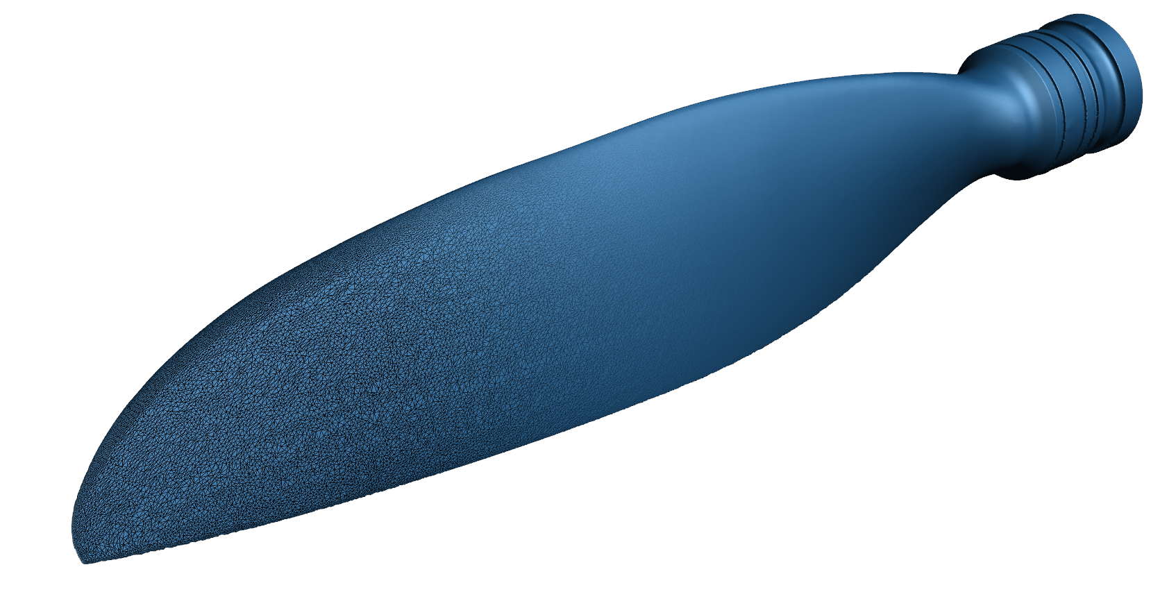
With targets placed on both sides of the blade, we can quickly gather surface geometry at 1.3 million data points per second. The latest in blue laser technology means no preparation to the shiny surface is required, and because we scan directly to a mesh, we don’t need to perform any point cloud conversions once complete. A simple deletion of unwanted data, namely the fixturing brackets, and a single click to begin the final processing yields a completed mesh less than five minutes after we begin scanning.
On a final note, if this were an operation that is to be repeated many times in a day, we can also mount our HandySCAN on a robot and program a repeatable scanning path to capture the data. That will not be necessary for the number of blades we expect to scan here but is always an option for high-quantity situations.
Once we’ve gathered our scanned mesh, we have a few workflow options. A mesh-to-mesh comparison is certainly possible, but we find that comparison to a CAD file is simply more efficient if repeating our analysis multiple times and is worth dedicating the resources to generating a usable CAD file. We can also use this model to manufacture our very own replacement parts upon approval, thus cutting down on the cost to stock and obtain OEM components.
This next step brings us to our premier reverse engineering tool, Geomagic Design X by Oqton. Design X allows us to create efficient solid and surface extractions via its fully automated and guided toolset, then utilize familiar 3D modeling techniques to bring that geometry together into a parametric CAD file.

To begin, we run the Auto Segment tool, which analyzes the mesh and breaks it up into regions that it recognizes to be singular geometries. The base of the blade root is seen as a Plane, the root hub is recognized as a Cylinder, and the sides of the airfoil are labeled as a Freeform surface.

The most useful tools for laying an accurate freeform surface down onto complex curvature are Mesh Fit and Loft Wizard. The Mesh Fit is excellent for quickly applying a freeform surface with a plethora of setting options to achieve a perfect fit, but once the surface is applied and the model is transferred to a downstream 3D environment, the ability to edit that surface is removed (more on this later.) If we’d like to retain the ability to make design changes, Loft Wizard is the ticket.
With the Loft Wizard, we can select the region(s) that represents one side of the airfoil and choose the number of cross sections we’d like to insert. This will be fine-tuned in the next stage, so an educated guess based on the complexity of the curvature will do for now.
As we move to the next stage of the wizard, we see a preview of the lofted surface with evenly spaced cross sections cutting through the region. With the Accuracy Analyzer turned on, a live deviation plot is applied to the surface to show exactly where it pulls away from the scan. By simply dragging and dropping existing cross sections, we can move or copy them to new locations until we eliminate all deviations. Once complete, we are left with an accurate parametric loft. This process is then repeated for the opposite side of the blade, as well as the blade base where it widens and connects to the root hub.

The Mesh Sketch projects the outer blade profile to a 2D reference sketch that we can trace with true sketch entities and extrude into a solid. The opposing blade surfaces created via the Loft Wizard can be used to then cut this solid back to the blade profile, as you would in any 3D modeling software.

The round root hub can quickly be extracted using another guided tool: the Revolution Wizard. This wizard instructs you to select the regions of the revolve that are to be modeled, after which the software inserts a new sketch and revolve to create the base.

Once merged, a 3D fillet can be applied to the junction between the hub and the blade base to create a smooth transition and eliminate a stress concentration point. To match the round in the scan, the Estimate Radius from Mesh function within the fillet is used to duplicate the radius and complete the model.
It’s at this point that any critical features can be adjusted to match that of our inspection criteria, as it’s highly unlikely that dimensions and profiles of the real part match exactly what our specified values should be.
As the final step, we then use Design X’s Live Transfer feature to send the model tree line-by-line into our native CAD software, leaving us with a model that can easily incorporate design changes later if desired.
Moving on to the final stage of our workflow, we will utilize Geomagic Control X to analyze subsequently scanned blades against our optimized nominal CAD model. Control X is an advanced quality control software that brings a comprehensive analysis toolset to a familiar CAD-like platform for shortened learning curves and efficient multi-piece inspection workflows.

We can import and add dimensions and tolerances directly to our new CAD file for automatic measurement upon the import of a new blade scan. Utilizing features under the Dimensions tab, we can apply a Datums and GD&T criteria to the blade root for purposes of checking profiles on the blade. Each of these features includes a tolerance range that will instantly display a pass/fail condition for each new scan.

Along with universal dimensions and GD&T, we can measure specific airfoil profile values with the Airfoil Analysis tool. Typical measurements such as Leading and Training Edge positions, Maximum Thickness, and Chord Length can be measured by simply clicking a check box. The software automatically determines these values from the cross section. Like the 3D dimensions, these values will all be updated and reported upon import of a new blade scan.

An indispensable Control X feature for detecting and analyzing surface damage, wear, and corrosion is Deviation Location. This tool applies a best fit surface to a targeted region of the measured mesh and reports standardized deviation callouts for these features. In this example, we can clearly see an area of the blade that took on damage and utilize Deviation Location to locate the pits greater than 1.5mm (roughly 0.06”) deep, then report both their maximum deviations and the locations of these points relative to the leading edge and blade tip.

Due to the individualized nature of this examination, Deviation Location can only be applied once our measured scan is imported and an initial observation for damage conducted.
All analyses are then sent to a preformatted report and saved in our contract catalog. This report will give your team an unparalleled understanding of not just whether the part passed or failed, but exactly why it failed. A collection of reports may even bring unknown wear trends to light, so as they can be more effectively addressed.

With our first blade inspection successfully complete, all additional incoming parts are automatically measured and reported with the ability to update snapshots, add additional Deviation Analysis locations, make notes, etc. If dozens of parts are to be scanned in a very short timeframe, Control X’s Visual Scripting and Batch Process capabilities can be leveraged to streamline and automate your workflow further.
Our shop is now set up to perform a preliminary investigation of each incoming blade to make an informed decision about whether they require simple reconditioning, if they need to undergo extensive repair, or whether a part is unsalvageable. The restored blades can then be scanned a second time to prove adherence to specifications before going out the door. This information can be determined immediately following a 5-minute scan, is not subject to human error, and can be saved indefinitely for future reference.
Industrial Applications in Action
Now that we’ve explored a scenario that would be vastly improved with our technology, we will explore a handful of customer success stories in which NeoMetrix Technologies has implemented our solutions and expertise to streamline real-world applications.
For our first example we will highlight our customer Advanced Composite Structures, Inc. who manufactures abrasion strips for helicopter rotor blades to aid in the extension of their operational lifespan. To properly design these strips, they first require accurate CAD data of the leading blade edges. I would like to point you to our case study HERE describing how NeoMetrix Technologies, Inc. utilized our Creaform MetraSCAN and Design X to create and deliver these files.
Advancing Aerospace Maintenance: Digitizing Helicopter Blades for Advanced Composite Structures
")
3D Scanning & Reverse Engineering an Aircraft
")
3D Scanning & Reverse Engineering of a Winglet Fitting
