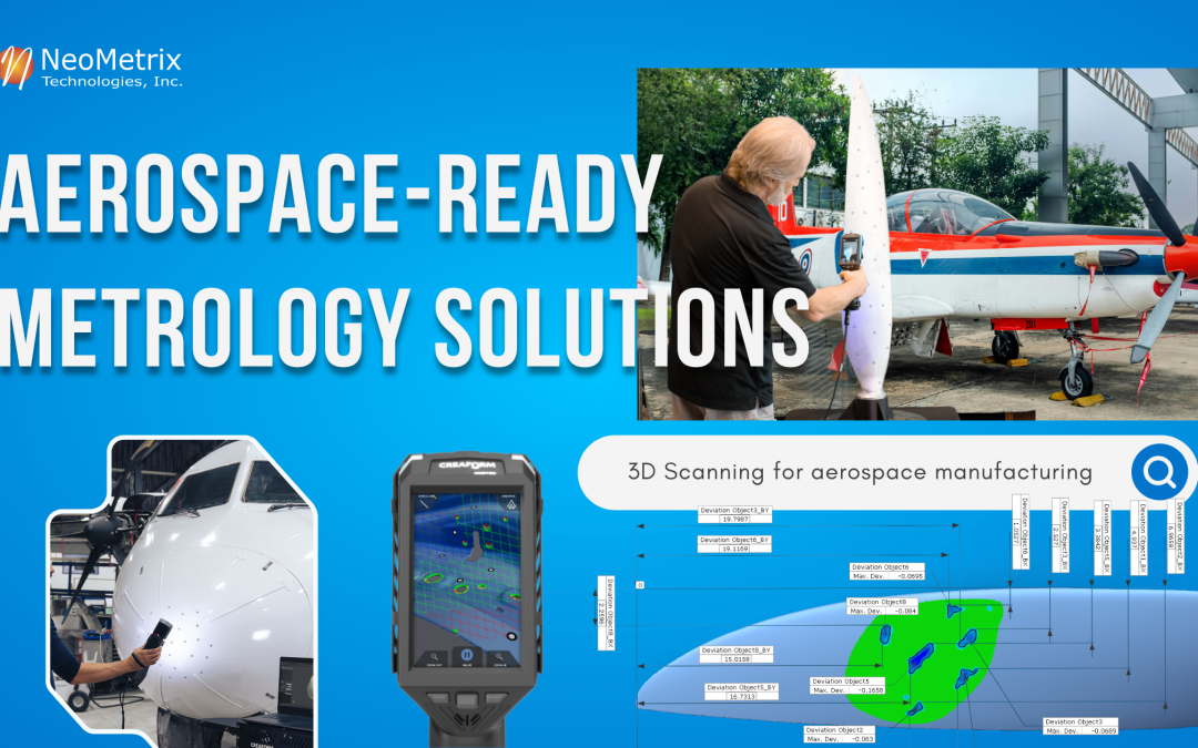
High-Accuracy Surface Analysis with HandySCAN EVO & Geomagic Control X
In aerospace manufacturing and MRO environments, inspection is critical to ensuring airworthiness, performance, and compliance. Components such as propellers, turbine blades, and aerodynamic surfaces operate within extremely tight tolerances—where even minor deviations can impact efficiency, vibration, and long-term reliability.
Traditional inspection methods often rely on limited point measurements, making it difficult to fully evaluate complex geometries or detect subtle surface damage. Today, high-resolution 3D scanning is transforming how aerospace engineers approach inspection and quality control.
Full-Field Inspection with High-Resolution 3D Scanning
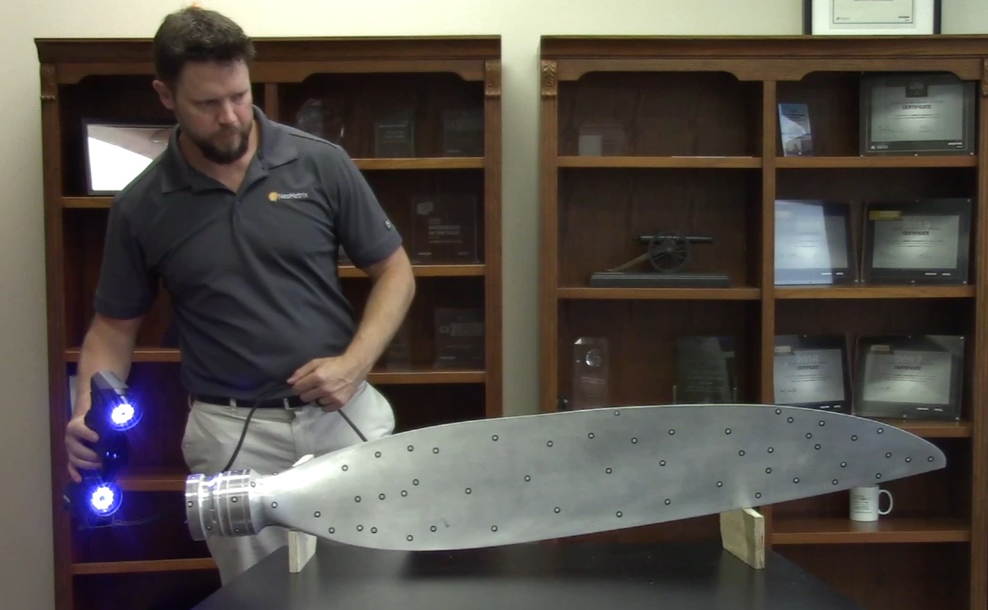
The HandySCAN EVO enables fast, accurate capture of full surface geometry—directly on the shop floor or in maintenance environments.
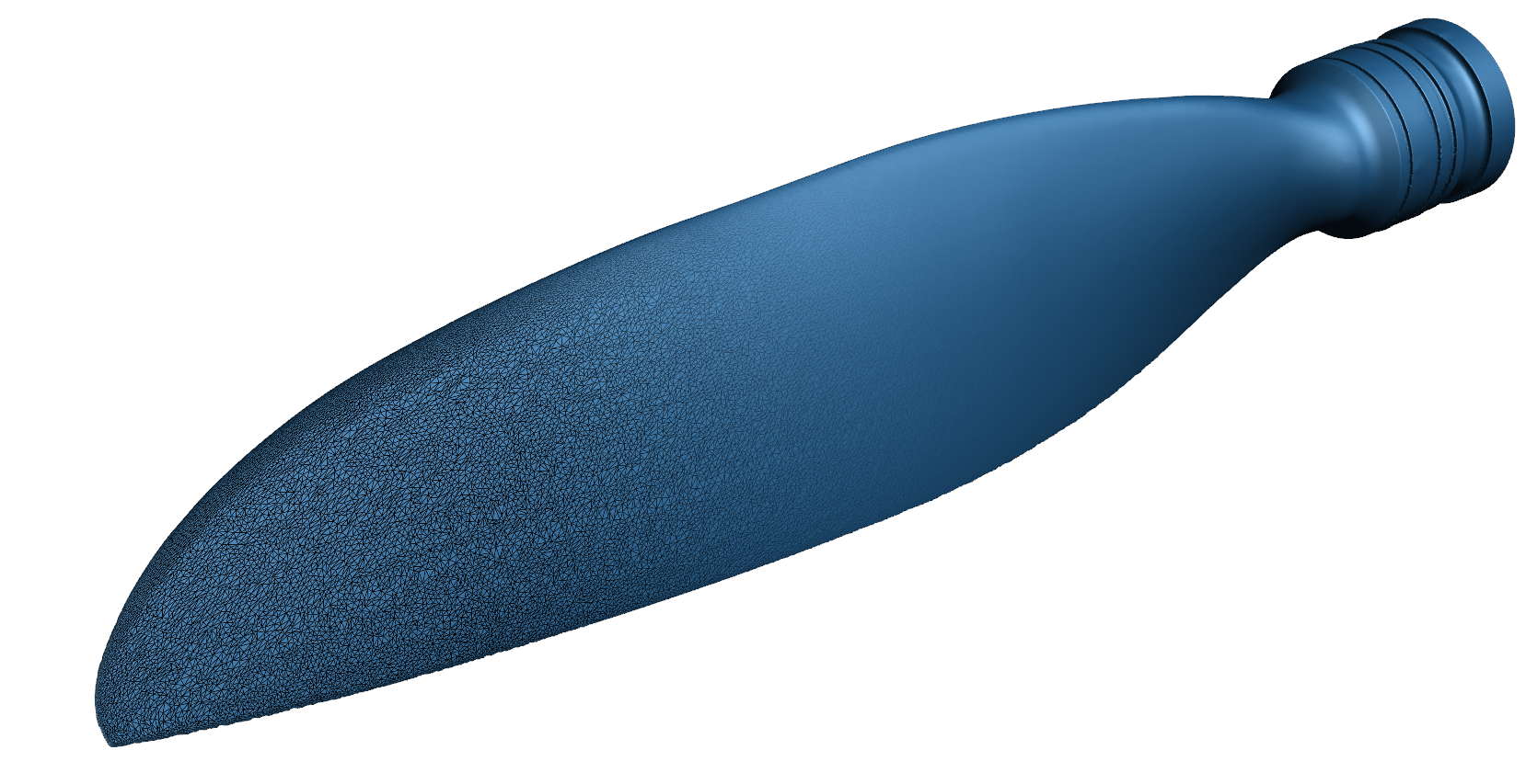
Unlike traditional tools, handheld 3D scanning captures millions of data points across the entire part, allowing engineers to analyze complete geometry rather than isolated features.
Key Capabilities:
- High-accuracy data acquisition across complex surfaces
- Rapid scanning of large and organic geometries
- Portable system for in-field or hangar inspection
- No need for rigid setups or controlled environments
In this example, a propeller is scanned to capture:
- Leading and trailing edge conditions
- Surface wear and deformation
- Overall geometry integrity

Deviation Analysis & Surface Damage Detection
Once scan data is captured, inspection shifts from measurement to analysis.
Using Geomagic Control X, engineers can compare scanned data against CAD models or nominal geometry to generate highly detailed inspection results.
What Engineers Can Analyze:
- Full color deviation maps across the entire surface
- Localized wear, erosion, or impact damage
- Dimensional accuracy against design intent
- GD&T-based inspection and reporting
Color maps provide immediate visual insight:
-
Positive/negative deviations clearly identified
-
Out-of-tolerance regions highlighted instantly
-
Surface damage zones quantified with precision
This enables faster root-cause analysis and more confident decisions in repair, replacement, or continued use.
Faster Inspection. Better Decisions. Reduced Downtime.
Benefits of 3D Scanning in Aerospace Inspection:
- Reduce inspection time compared to traditional methods
- Improve accuracy with full-field data capture
- Minimize rework and unnecessary part replacement
- Accelerate maintenance and validation cycles
- Support compliance with documented, repeatable reports
Instead of relying on limited measurement points, engineers gain complete digital visibility into part condition.
From Inspection to Actionable Data
Modern inspection is not just about identifying issues—it’s about delivering clear, actionable insights.
With integrated scanning and inspection software:
- Reports are generated quickly and consistently
- Data can be shared across engineering and QA teams
- Digital records support traceability and compliance
- Reverse engineering workflows can begin immediately if needed


Geomagic Control X is utilized to analyze subsequently scanned blades against our optimized nominal CAD model. Control X is an advanced quality control software that brings a comprehensive analysis toolset to a familiar CAD-like platform for shortened learning curves and efficient multi-piece inspection workflows.

We can import and add dimensions and tolerances directly to our new CAD file for automatic measurement upon the import of a new blade scan. Utilizing features under the Dimensions tab, we can apply a Datums and GD&T criteria to the blade root for purposes of checking profiles on the blade. Each of these features includes a tolerance range that will instantly display a pass/fail condition for each new scan.

Along with universal dimensions and GD&T, we can measure specific airfoil profile values with the Airfoil Analysis tool. Typical measurements such as Leading and Training Edge positions, Maximum Thickness, and Chord Length can be measured by simply clicking a check box. The software automatically determines these values from the cross section. Like the 3D dimensions, these values will all be updated and reported upon import of a new blade scan.

An indispensable Control X feature for detecting and analyzing surface damage, wear, and corrosion is Deviation Location. This tool applies a best fit surface to a targeted region of the measured mesh and reports standardized deviation callouts for these features. In this example, we can clearly see an area of the blade that took on damage and utilize Deviation Location to locate the pits greater than 1.5mm (roughly 0.06”) deep, then report both their maximum deviations and the locations of these points relative to the leading edge and blade tip.

Due to the individualized nature of this examination, Deviation Location can only be applied once our measured scan is imported and an initial observation for damage conducted.
All analyses are then sent to a preformatted report and saved in our contract catalog. This report will give your team an unparalleled understanding of not just whether the part passed or failed, but exactly why it failed. A collection of reports may even bring unknown wear trends to light, so as they can be more effectively addressed.

With our first blade inspection successfully complete, all additional incoming parts are automatically measured and reported with the ability to update snapshots, add additional Deviation Analysis locations, make notes, etc. If dozens of parts are to be scanned in a very short timeframe, Control X’s Visual Scripting and Batch Process capabilities can be leveraged to streamline and automate your workflow further.
Our shop is now set up to perform a preliminary investigation of each incoming blade to make an informed decision about whether they require simple reconditioning, if they need to undergo extensive repair, or whether a part is unsalvageable. The restored blades can then be scanned a second time to prove adherence to specifications before going out the door. This information can be determined immediately following a 5-minute scan, is not subject to human error, and can be saved indefinitely for future reference.

Industrial Applications in Action
Now that we’ve explored a scenario that would be vastly improved with our technology, we will explore a handful of customer success stories in which NeoMetrix Technologies has implemented our solutions and expertise to streamline real-world applications.
For our first example we will highlight our customer Advanced Composite Structures, Inc. who manufactures abrasion strips for helicopter rotor blades to aid in the extension of their operational lifespan. To properly design these strips, they first require accurate CAD data of the leading blade edges. I would like to point you to our case study HERE describing how NeoMetrix Technologies, Inc. utilized our Creaform MetraSCAN and Design X to create and deliver these files.
Advancing Aerospace Maintenance: Digitizing Helicopter Blades for Advanced Composite Structures
")
3D Scanning & Reverse Engineering an Aircraft
")
3D Scanning & Reverse Engineering of a Winglet Fitting
Aerospace Inspection Solutions – Equipment & Services
NeoMetrix provides both equipment and engineering services for aerospace inspection and quality control:
Solutions Include:
- High-accuracy 3D scanning systems
- Advanced inspection and metrology software
- Scan-to-CAD and reverse engineering services
- On-site or outsourced inspection support
Whether inspecting in-service components or validating new designs, accurate surface data is essential to maintaining performance and safety standards.

Request an Inspection or Demo
Have a component that needs inspection, validation, or reverse engineering?