
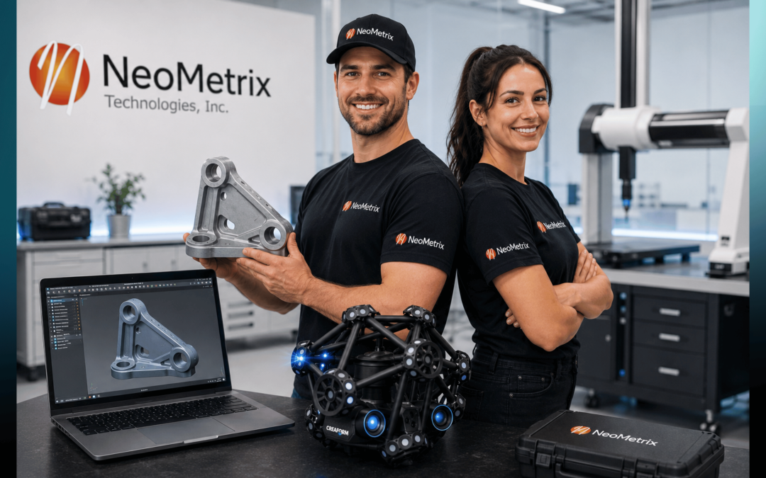
Manufacturers rarely struggle because they lack data. The real challenge is turning physical parts, tooling, and assemblies into digital information they can actually use.
A component may need to be recreated without its original drawings. A manufactured part may need to be compared against its CAD model. A legacy tool may need to be modified, reproduced, or replaced. In each case, the most effective solution is not a single piece of equipment or software—it is a connected workflow built around 3D scanning, CAD, reverse engineering, and computer-aided inspection software.
Together, these technologies create a practical bridge between the physical and digital worlds. They help engineering and quality teams understand what exists, identify what has changed, and determine what needs to happen next.
Here's a closer look - Rotate, Pan, Zoom
The Digital Thread Begins with the Physical Part
Traditional measurement methods remain useful, but complex surfaces, organic geometry, worn components, and large assemblies can be difficult and time-consuming to document manually.
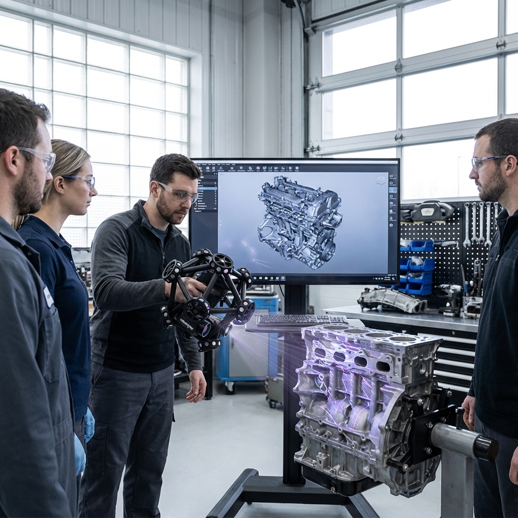
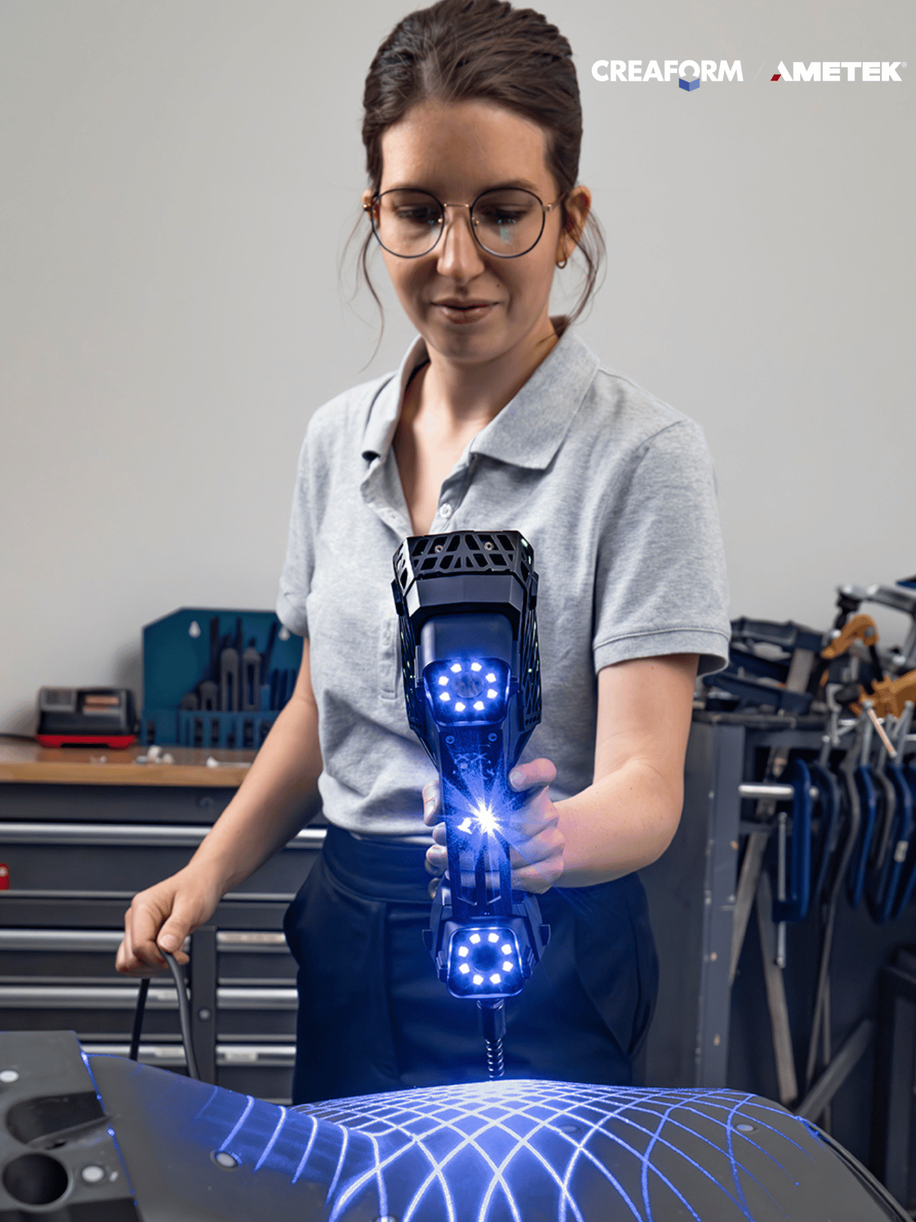
Industrial 3D scanning captures dense surface data across an entire part. Instead of measuring only a limited number of individual points, the scanner creates a detailed digital representation of the component’s visible geometry. This scan data can then support several downstream applications, including:
- Recreating missing or outdated CAD files
- Comparing a manufactured part to its original design
- Documenting tooling, fixtures, molds, and legacy components
- Evaluating wear, deformation, or production variation
- Modifying an existing product or component
- Creating digital records of physical assets
The scan is the starting point. Its real value comes from what engineering and quality teams do with the captured data.
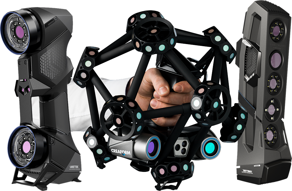
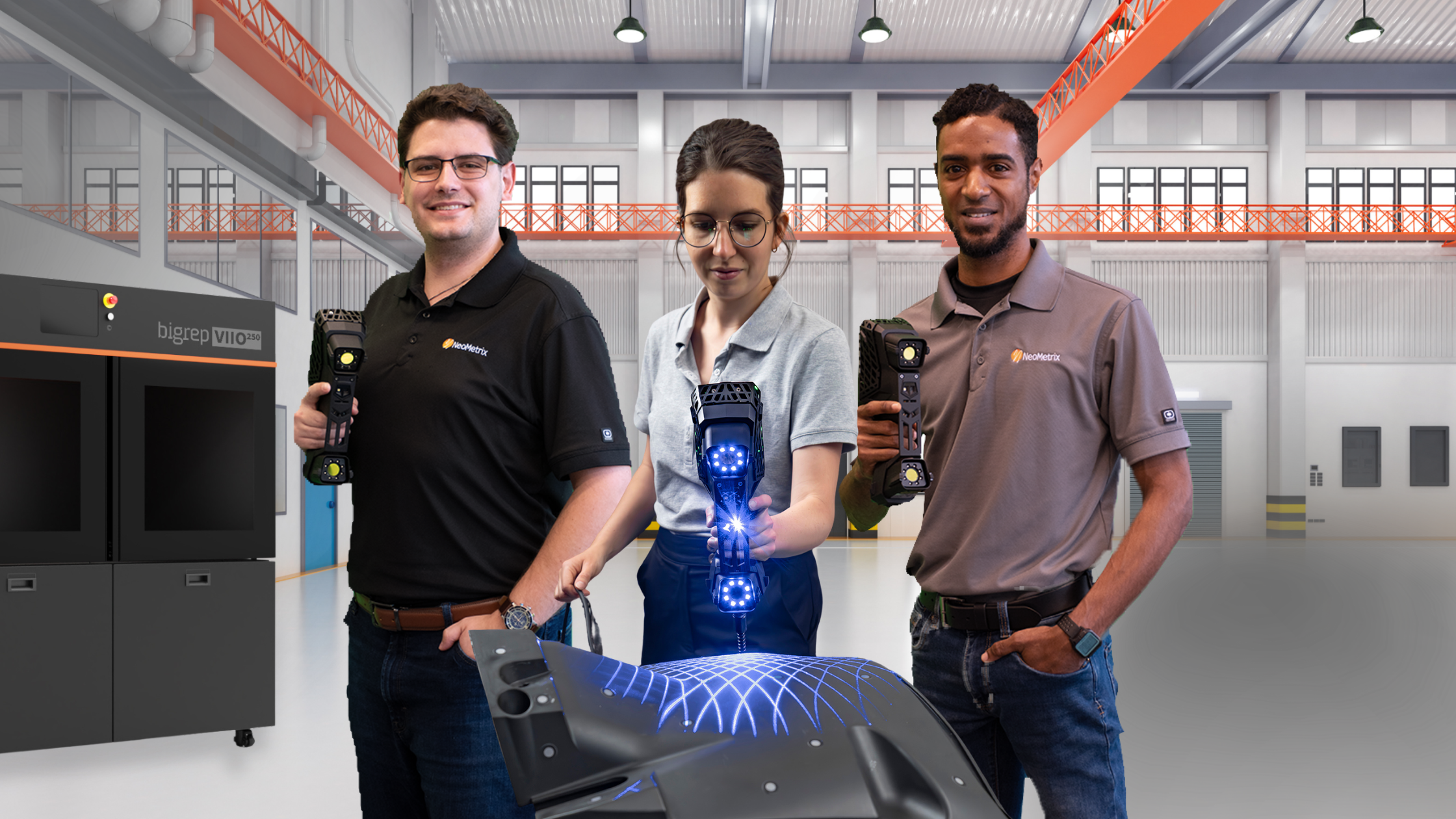
Creaform 3D Scanners
Reverse Engineering: Turning Scan Data into Usable CAD
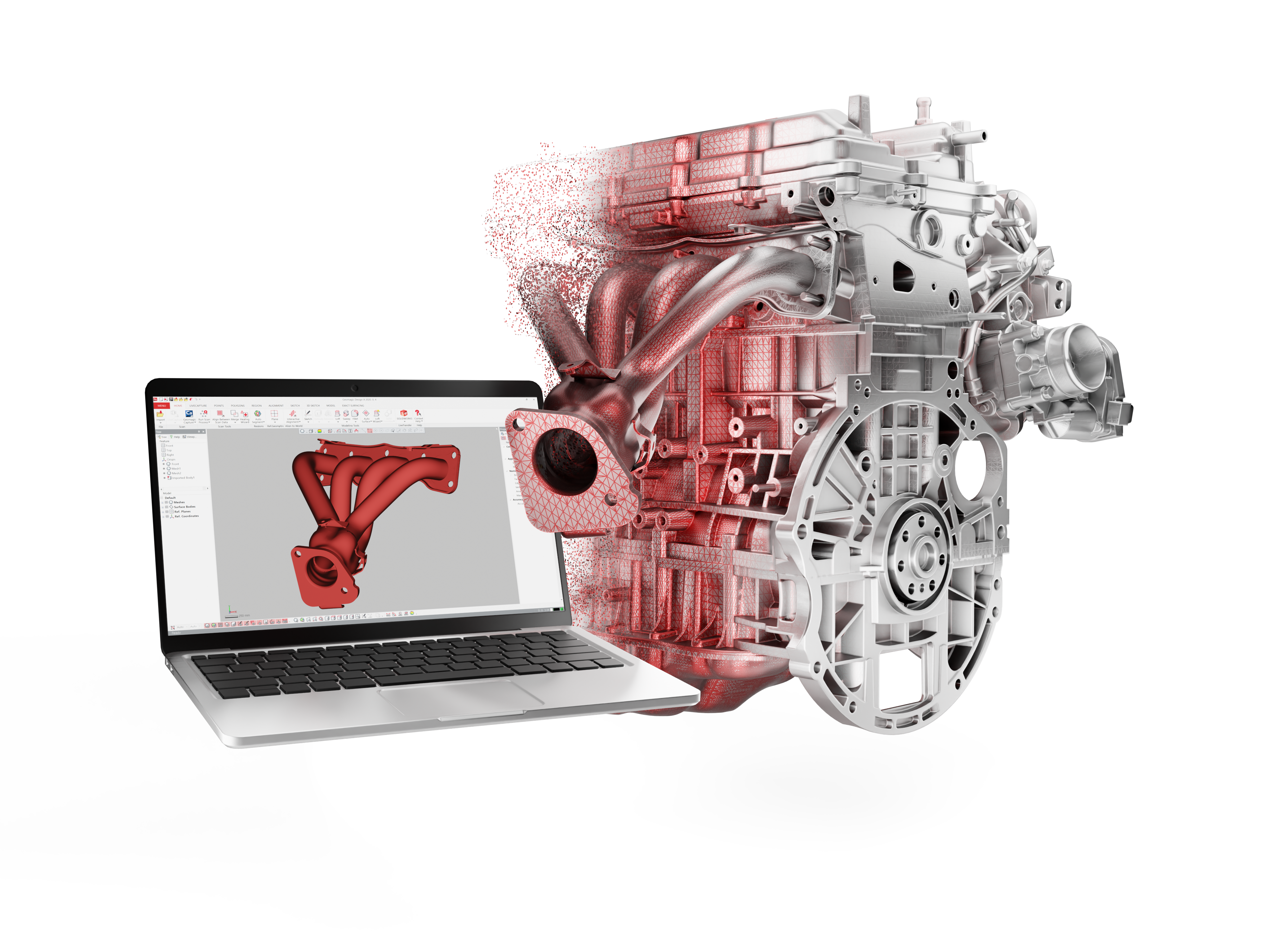
Capturing a part is not the same as rebuilding its design intent. A 3D scan commonly begins as a point cloud or polygon mesh. That data accurately represents the physical surface, but most engineering teams need an editable CAD model they can modify, manufacture, analyze, or place within an assembly.
This is where reverse engineering creates value.
Through a scan-to-CAD process, engineers can use the captured geometry as a reference for rebuilding features such as planes, cylinders, holes, fillets, patterns, and complex surfaces. Depending on the project, the final deliverable may be a clean surface model, a solid model, or a fully parametric CAD model with editable features.
Reverse engineering is especially useful when:
- Original drawings or CAD files are unavailable
- A supplier no longer supports a critical component
- An older part needs to be reproduced or improved
- Tooling has worn or changed after years of use
- A physical prototype must become a manufacturable design
- A component must be adapted to fit a new assembly
The goal is not merely to duplicate every dent, scratch, or imperfection. A strong reverse-engineering process distinguishes between the part as it currently exists and the part as it was intended to function.
That distinction is what transforms raw scan data into useful engineering information.
Need an editable CAD model from an existing part?
Reverse Engineering: From Mesh to Manufacturing-Ready CAD
Once scan data is captured, it becomes a powerful engineering asset.
Reverse engineering tools convert raw mesh data into fully parametric CAD models, enabling:
- Redesign of legacy or undocumented parts
- Design modifications based on real-world geometry
- Rapid recreation of worn or damaged components
- Optimization of complex surfaces and organic shapes
Instead of rebuilding designs from scratch, engineers can work from exact digital representations of physical parts, dramatically reducing design time and risk.
Computer-Aided Inspection: Seeing More Than Pass or Fail
Reverse engineering answers the question, “How can we recreate or modify this part?”
Computer-aided inspection answers a different question: “Does this manufactured part match its intended design?”
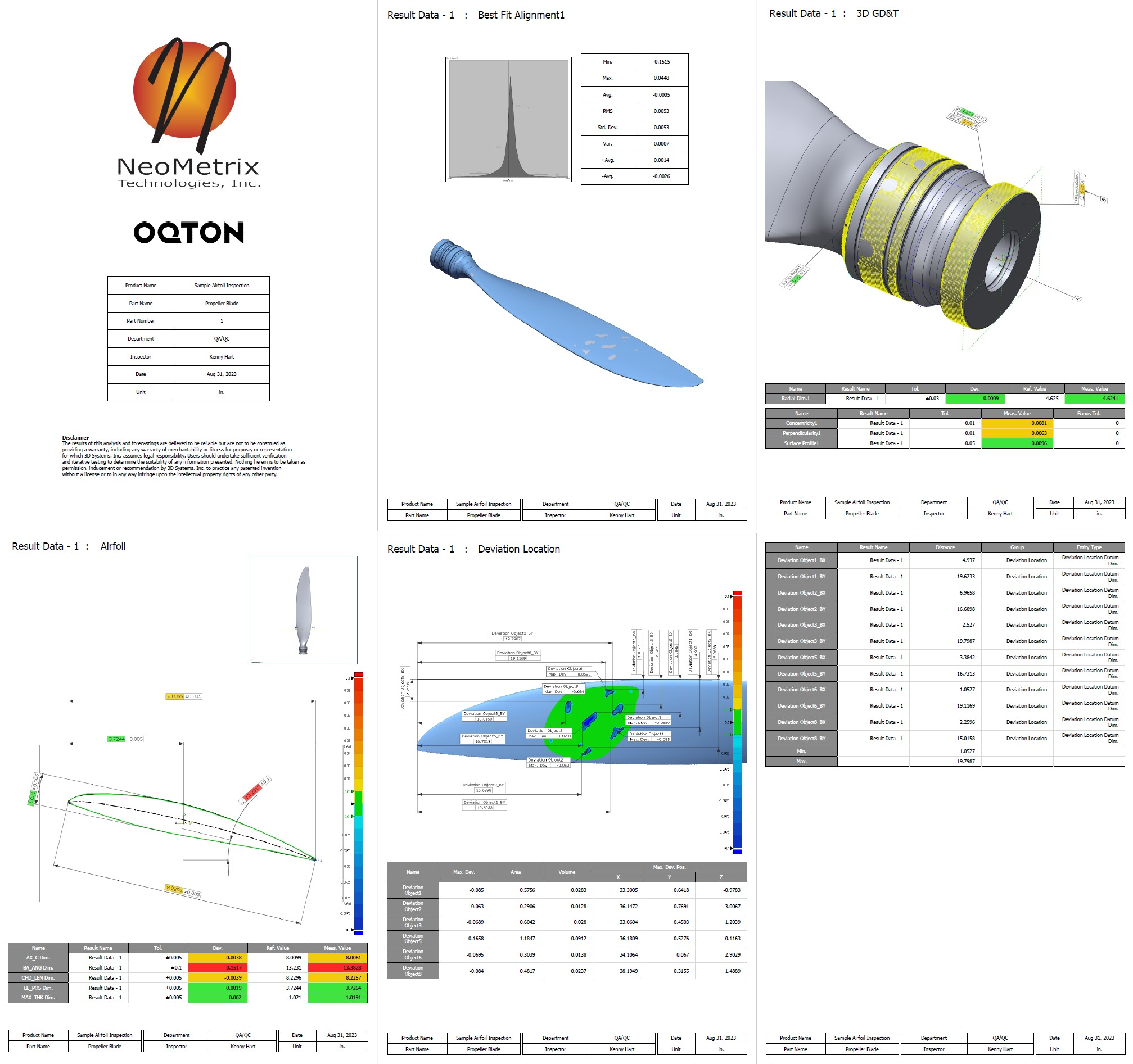
In a digital inspection workflow, scan data from the manufactured component is aligned with the nominal CAD model. Inspection software then calculates the differences between the two surfaces.
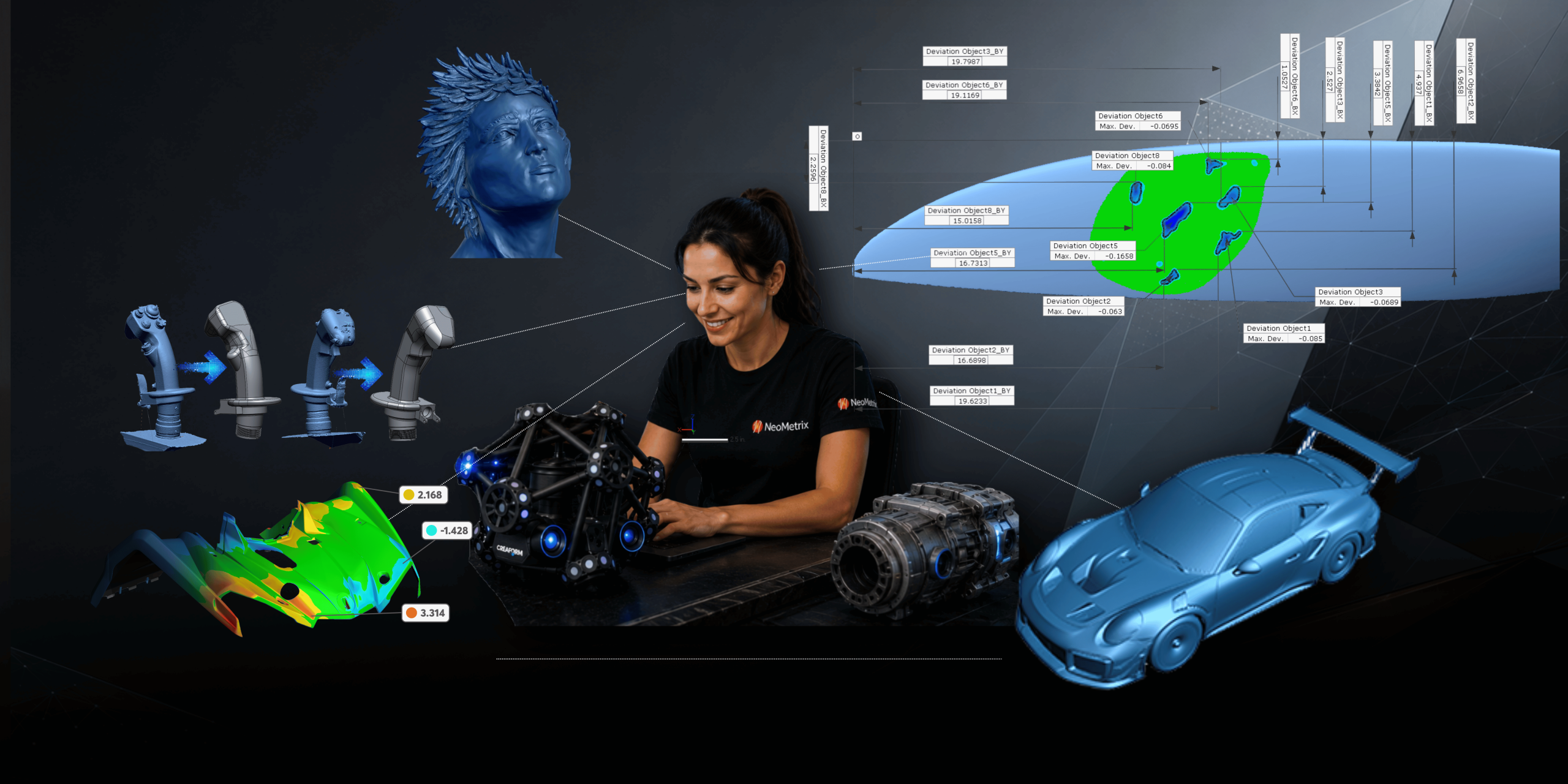
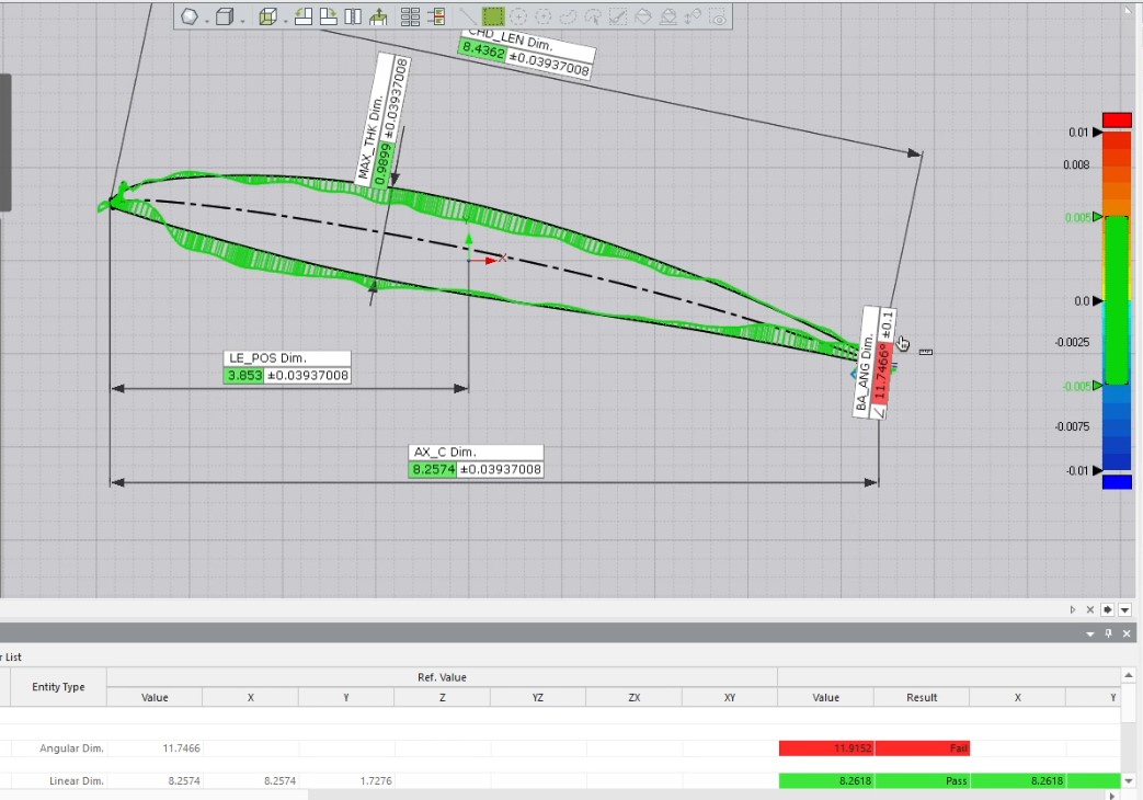
The result is a visual and measurable picture of part quality. Color deviation maps can quickly reveal areas that are above or below tolerance, while cross-sections and dimensional callouts provide more detailed verification of critical features.
This approach can help teams:
- Detect warping, shrinkage, or deformation
- Verify complex contours and freeform surfaces
- Evaluate tooling and molded components
- Compare prototype iterations
- Investigate assembly or fit problems
- Document first-article and production-part quality
- Communicate inspection findings through clear reports
Instead of relying only on a pass-or-fail result, engineers can see where a deviation occurs, how large it is, and whether it follows a broader pattern. That context can make it easier to identify the source of a manufacturing problem and make informed process adjustments.
Turn physical-part data into clear, actionable inspection results.
Geomagic Software Connects the Workflow
The transition from scan data to engineering output depends heavily on software.
Geomagic solutions support two of the most important paths in the 3D scanning workflow:

Easily build custom reports!

Easily build custom reports!
One Data Capture, Multiple Engineering Possibilities
One of the strongest advantages of a connected digital workflow is that the same scan data may support more than one objective.
Consider an aging component that no longer has usable design files. The part can be scanned and reverse engineered into an editable CAD model. That model can be updated for a replacement manufacturing process. Once the new component is produced, it can be scanned again and inspected against the newly created CAD data.
The workflow becomes:
-
Capture the physical component with a 3D scanner.
-
Reconstruct its design in CAD through reverse engineering.
-
Modify or manufacture the part using the new digital model.
-
Inspect the finished component against the CAD definition.
-
Document the results for future production and quality control.
What begins as a physical part becomes a reliable digital asset that can support engineering, manufacturing, and inspection throughout the product lifecycle.
Should You Invest in Equipment, Software, or Services?
The right approach depends on how often your team needs the technology, how quickly results are required, and whether you have the internal resources to manage the workflow.
Purchasing 3D scanning equipment and software may make sense for organizations with recurring inspection, product development, tooling, or reverse-engineering needs. Internal capability offers greater scheduling control and lets teams use the technology across multiple departments and applications.
Professional services may be the better fit when the need is project-based, the part requires specialized expertise, or results are needed without adding new equipment and training responsibilities.
Some organizations use both: internal scanning for everyday needs and an experienced metrology partner for complex projects, overflow work, onsite capture, or specialized CAD and inspection deliverables.
- Do you need to recreate it?
- Modify it?
- Compare it to CAD?
- Find the cause of a fit or quality problem?
- Establish an internal scanning and inspection capability?
From there, the right combination of 3D scanning, CAD, reverse engineering, and inspection becomes much clearer.
NeoMetrix Technologies helps manufacturers connect these technologies into practical workflows—from selecting and implementing industrial 3D scanning equipment and Geomagic software to completing reverse-engineering and computer-aided inspection projects.
Have a part, project, or production challenge to solve?
Connect with a NeoMetrix engineer for a complimentary consultation and discover the most direct path from physical geometry to usable results.