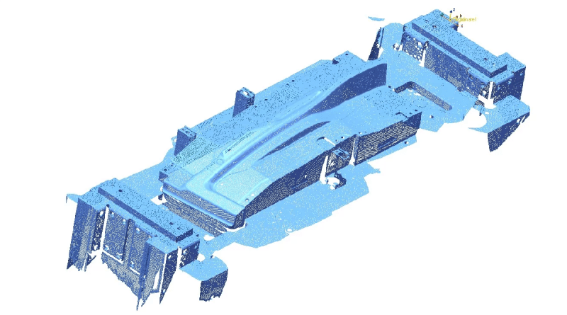
The automotive field is dependant on a multitude of manufacturing industries. Hot stamping is a common process in the race towards safer and more efficient cars. The process is made up of transforming a thin, low-tensile-strength metal into high-strength steel through heat using a press and die set. By doing the stamp while the steel is nearly molten, the process eliminates springback and allows ability for the creation of complex geometries.
Gestamp, international group dedicated to the design, development and manufacture of metal automotive component, produces chassis, mechanism and body-in-white parts for the main auto manufacturers. They manufacture bumper beams, crash boxes and door ring components.
 For die replacement or manufacturing, hot stamping companies like Gestamp undergo the same difficulties: they have to rely on early die drawings that may or may not be up to date, and also may have a hint of unavoidable human error.
Disadvantages of Relying on Original Drawings
It’s important to have your manufacturing team on the same page. When changes are made in a product, it’s normal in the past that adjustments have not been accuratley recorded or documented between the CAD Model and the actual die used in production.
Without this information, how can the die improvement or replacement process be managed efficiently? What would be an efficient alternative to this process? What is the cost and timetable for the implementation of a substitute solution?
Good news: 3D scanning systems and reverse engineering are key tools in industries where quality and purpose are based on meticulous precision.
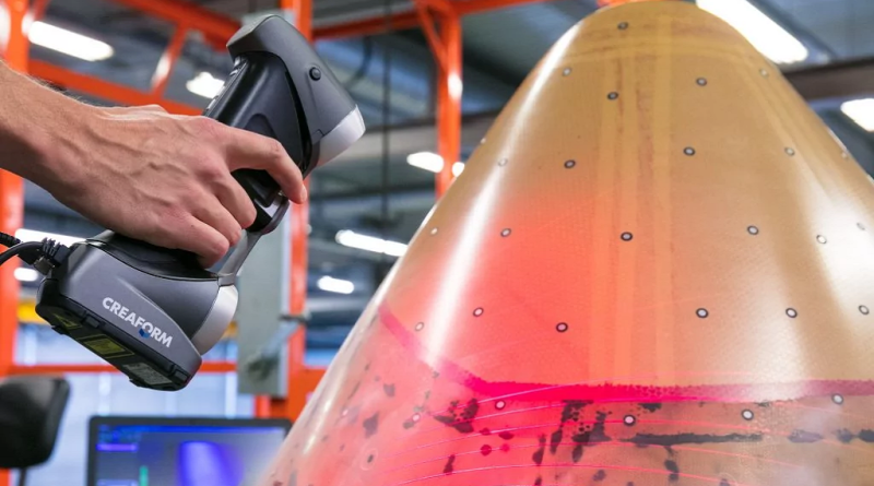
Creaform HandySCAN aquiring data to adjust and reproduce a part
A Classic Approach to Production
Just like most design-to-production workflows in manufacturing environments, hot stamping has traditional steps that should work seamlessly:
- The stamping plant receives a CAD for a new part – a work order of sorts.
- Engineers use the model to design the die that will be used to stamp the part.
- The 3D model of the die is sent to the die manufacturer.
- Once built, the actual die is sent to the stamping plant where it goes through inspection, quality control and fine-tuning.
- The die is submitted to the customer’s approval before going into the production environment, where it will be used to produce precise parts, matching the exact specifications.
Does this look like an efficient process to you? The problem occurs after the die is in place and used in the hot stamping process, i.e., when the die needs to be adjusted or replaced.
Back up Your Actual Die With a 3D Scanned Model File
Among other things, the replacement of a die can result from a partial or total damage, the end of life of the die, or a large rise in demand which requires the manufacturing of an identical die to meet the increasing needs.
Without having a CAD model to rely on, the engineers have to use the initial design of the die to produce a new one. This ends up being a time-consuming, costly and frustrating mistake which will have a negative impact on the end result.
Worst case scenario, since the former die is either broken or unusable by now, it is necessary to go through the whole cycle again from the beginning.
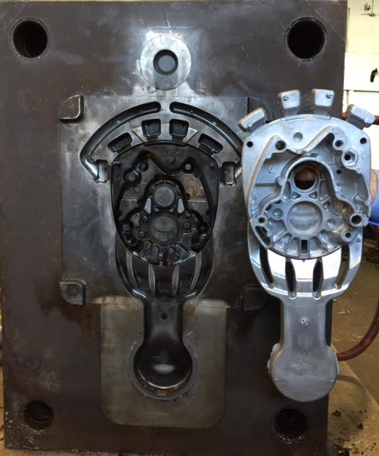
Human Errors in Engineering
It is confirmed that the central issue has to do with the adjustment data not being accounted for at some point in the process.
Two Common Mistakes:
The engineers who perform the inspection, QC, and fine-tuning steps, work under extreme pressure and sometimes fail to effectively collect and document all modifications made during the development phase.
The modifications are collected, documented and transmitted to the engineering department, but the engineers fail to update the original drawings due to a lack of resources.
3D Scanning and Reverse Engineering to the Rescue
Without a doubt, the missing step in the chain is the clear, mandatory communication of updated features to the engineering department. Just about any workflow is exposed to human error, the situation calls for a streamlined process enhanced by the right technology tools for the job.
Technical managers of stamping operations at Gestamp decided to turn things around and pursue new avenues such as 3D scanning. They added several steps to the traditional process:
- Once the die is adjusted and producing parts within specifications, it is scanned, and all the modifications made are recorded.
- The output mesh file corresponding to the scanned surface can be used to reverse engineer the die including its slightest details.
- The surface is incorporated into the initial 3D model of the die.
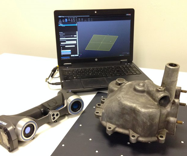
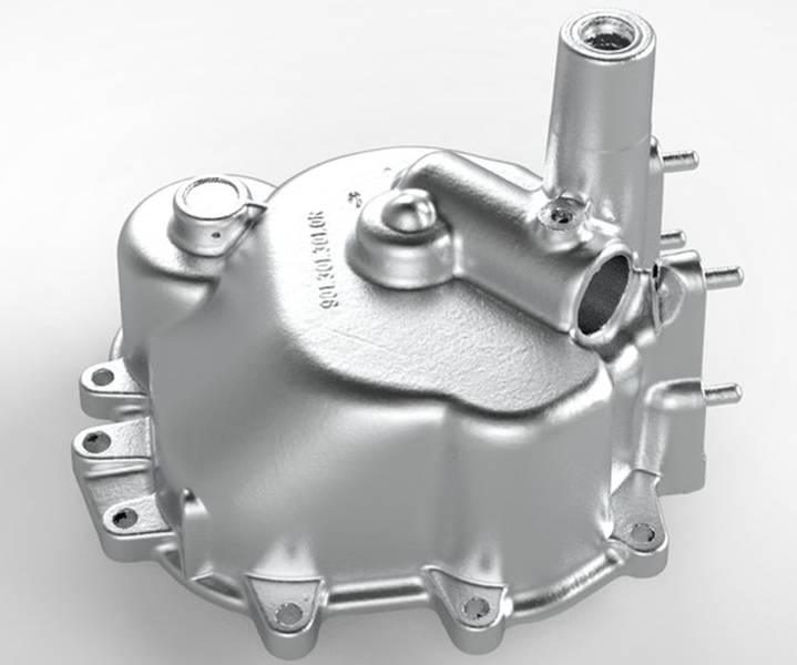
For Gestamp managers, the benefits are obvious: the high-precision and portability of 3D scanners by Creaform:
Plus availability of increasingly sophisticated reverse engineering software like GeoMagic Design X aimed at the process of transforming scanned surfaces into data.
Therefore, when a die is already adjusted to the specifications and actively producing parts, it can be scanned right on the shop floor to record and crystallize the modifications made to the former die. Instantly, an updated CAD can be made available.
Bottom line, with the pinpoint accuracy of Creaform’s solution, the adjustment phase of the new dies manufactured for Gestamp is considerably shorter, if not completely removed. This means more time for the engineers to spend on higher prioritiezed tasks, and less finances down the drain.
Source: https://metrology.news/reverse-engineering-using-3d-scanning-provides-missing-link-in-hot-stampings/
For more information about the 3D solutions offered by NeoMetrix:
