Scanning & 3D Modeling a Carbon Fiber Drone Blade
Creating a CAD Model of Complex Part Made Easy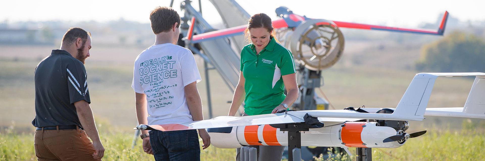
Students inspecting a drone before takeoff from the Unmanned Aircraft System Operations at the University of North Dakota.
THE PROBLEM
Engineering students at the University of North Dakota were working on a project that required an accurate 3D CAD model of a carbon fiber propeller blade for a drone.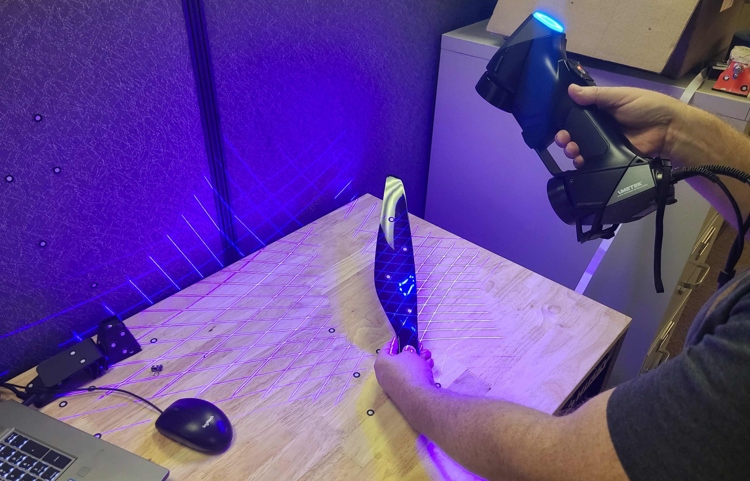
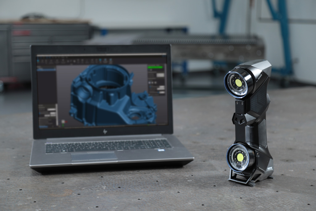
3D Scanning solution from the NeoMetrix team using the Creaform HandySCAN Black Elite
TRADITIONAL METHOD
Without a coordinate measuring machine of some type, it’s virtually impossible to accurately create a CAD file of something as complex as a propeller blade. Some destructive methods could be employed to cut up a blade, then trace the cross sections of the airfoils, then somehow enter those profiles into a CAD system. This may yield a CAD model, but the geometry would be no where close to the original.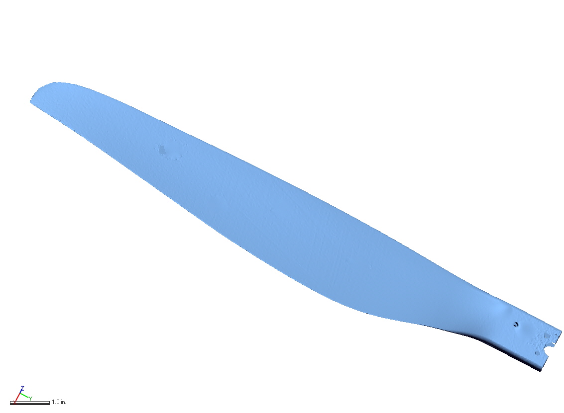
STL From Scan
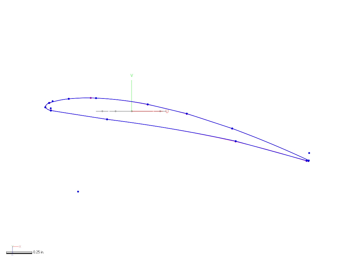
Airfoil Cross-Section
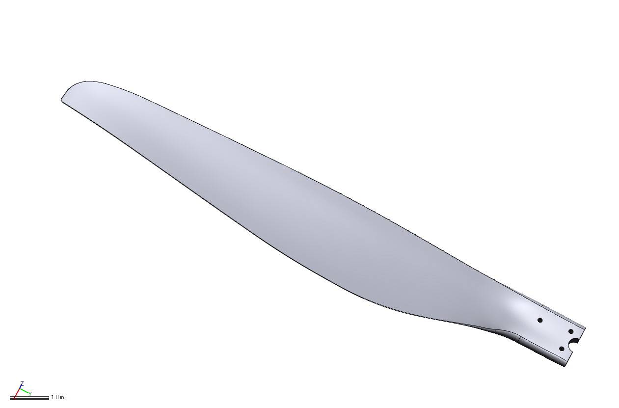
Final Solid Model
NEOMETRIX SOLUTION
A scanner like the Creaform HandyScan Black Elite, enables engineers to capture the most complex shapes, quickly and easily. The initial output from VX Elements, Creaform’s data collection software, is an STL file. This STL is then be imported into Geomagic Design X in order to develop the 3D CAD. Complex surfaces can be created by several methods, such as lofting between cross-sectional sketches, or by using advanced surfacing methods that fit NURBS surfaces direction onto the scanned STL. The final CAD model can then be exported in common formats like STEP or IGES, or Live-Transferred into common CAD software programs like Solidworks or CREO.
NEOMETRIX ADVANTAGE
By employing 3D scanning technology for this application, engineers can develop required 3D CAD models faster and more accurately then with traditional methods. A more accurate CAD file means better downstream results for activities like Computational Fluid Dynamics, Finite Element Analysis or 3D printing of duplicates.Want to Learn More About 3D Scanning Solutions?

