Problem:
A power plant was due for updates and modifications. Accurate 3D CAD models of the “AS-BUILT” condition were required to design upgrades.
Traditional Method:
Technicians must measure all components with hand tools and tape measures, and then manually enter data into CAD. Virtually impossible to model every wire and hose accurately.
NeoMetrix Solution:
- Large components were scanned on site using a Leica long range laser scanner.
- Scan Data is registered, merged, and aligned in Rapidform XOR. (Figure 1)
- Each and every tube, wire, and fuel line was modeled. (Figure 2)
- Model is aligned to the customer specified coordinates to meet existing refit models. (Figure 3)
NeoMetrix Advantage:
- Less labor intensive, quicker turnaround time, and a much greater degree of accuracy than traditional methods
- 3D model available for design changes, checking clearances, and refit space claim
Get Started Today!
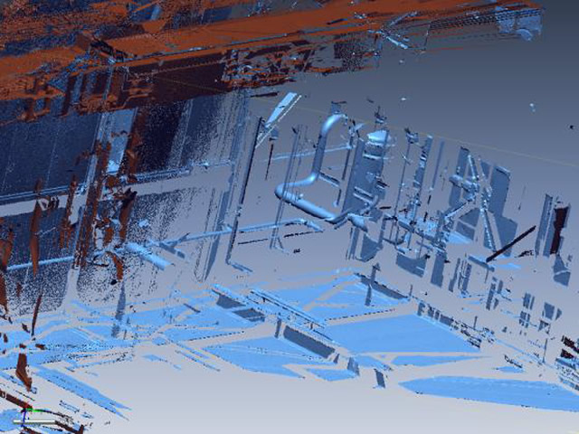
Figure 1 – Raw Scanned Data
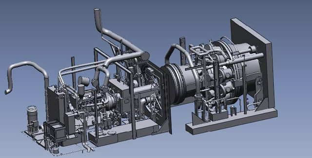
Figure 2 – High Detail Modeling
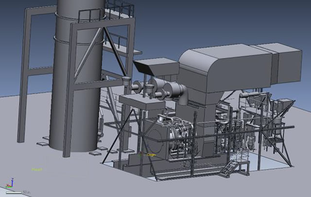
Figure 3 – Global Alignment
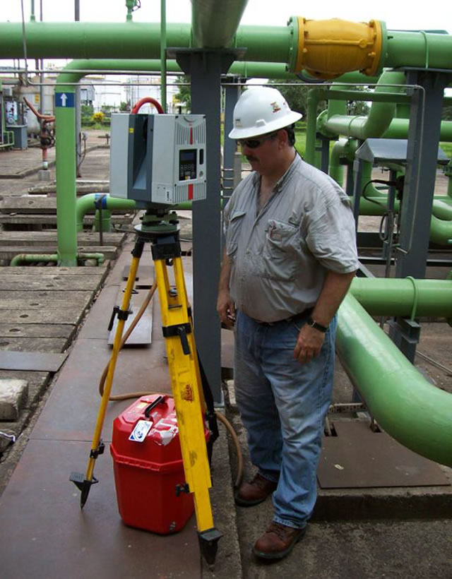
Figure 4 – Scanning
The scanner is positioned to take multiple scans from various positions.
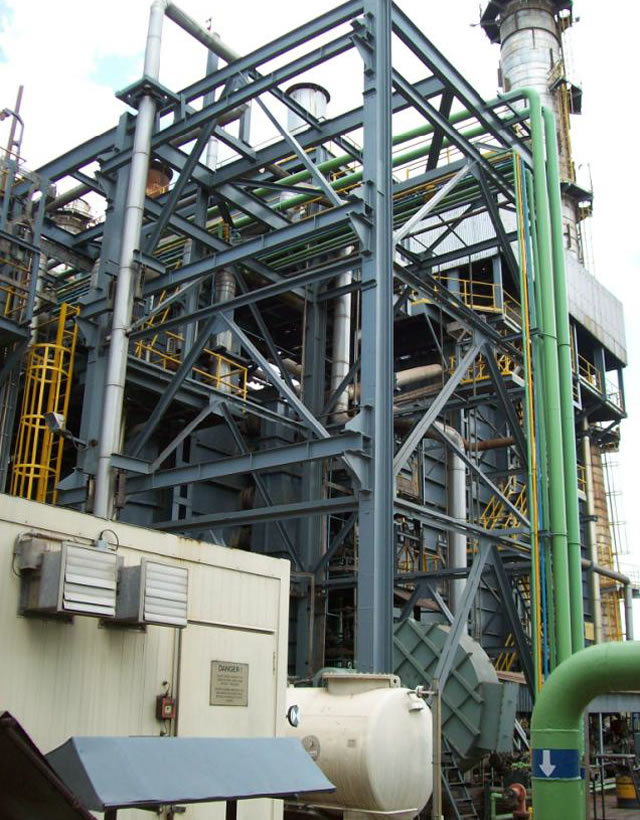
Figure 5 – Tower
Outside of the large tower
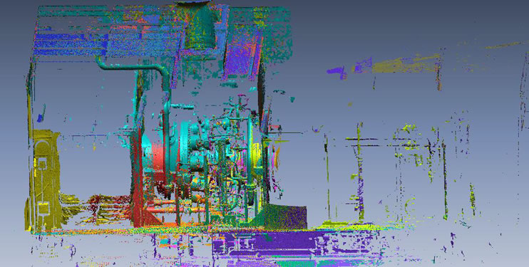
Figure 6 – Raw Scan Data
After scanning the data is aligned in the correct position to gather enough information to create an accurate model.(
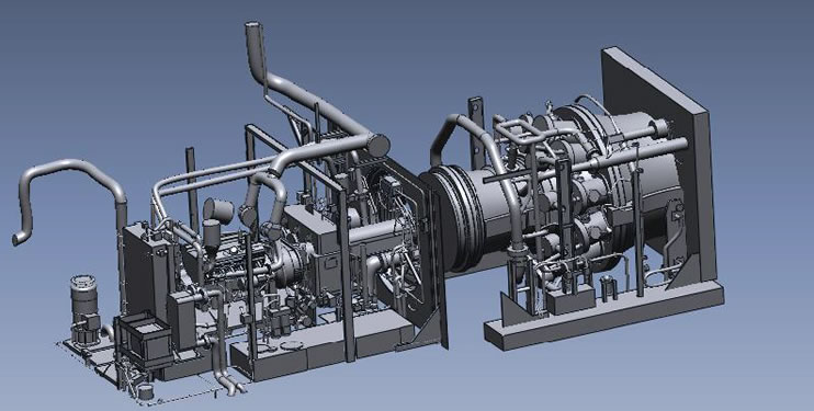
Figure 7 – Starter Room and Turbine
Each pipe/wire/tube/fuel line were all modeled so the engineers would know exactly where they had open space to add re-fit components.